This guide outlines the key principles and practical considerations for navigating the diverse world of RF connectors, starting with understanding their standardized nomenclature.
Selecting the optimal RF coaxial connector is a critical decision in the design and maintenance of any wireless communication, test and measurement, or high-frequency electronic system. The right choice ensures signal integrity, minimizes power loss, and guarantees system reliability, while the wrong connector can lead to performance degradation, interoperability issues, and costly rework. This guide outlines the key principles and practical considerations for navigating the diverse world of RF connectors, starting with understanding their standardized nomenclature.
Understanding RF Connector Nomenclature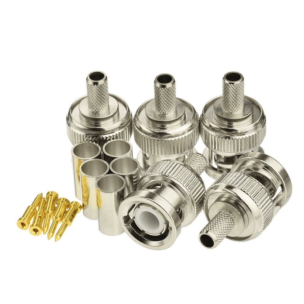
RF coaxial connector models follow a structured naming convention, consisting of a Main Name Code and a Structure Code, separated by a dash ("-"). The Main Name Code (e.g., SMA, N, TNC) is derived from international standards and identifies the connector series or interface standard. The Structure Code provides details about specific physical characteristics, such as the gender (plug or jack), mounting style (panel mount, cable mount), or contact termination (solder cup, crimp). Familiarity with this system is the first step in accurately specifying and sourcing the correct component for your application.
A Step-by-Step Framework for RF Connector Selection
1. Prioritize Electrical Performance Specifications
The core of your selection must be driven by electrical requirements.
- Frequency Range: Always choose a connector rated for your system's maximum operating frequency. Exceeding this limit can result in increased VSWR and signal mode generation.
- Voltage Standing Wave Ratio (VSWR): Opt for connectors with the lowest possible VSWR (closest to 1:1) to ensure maximum power transfer and minimal signal reflection. Precision connectors typically offer superior VSWR performance.
- Insertion Loss: Select connectors designed to minimize signal attenuation, especially critical in long cable runs or low-power applications.
- Impedance Matching: Ensure the connector's characteristic impedance (typically 50Ω or 75Ω) matches that of the connected cable and system components to prevent reflections.
2. Evaluate Mechanical and Environmental Requirements
Physical and operational demands are equally important.
- Connector Style: Straight connectors generally offer slightly better electrical performance, but right-angle (elbow) connectors are essential for saving space and managing cable routing in tight enclosures.
- Coupling Mechanism: The locking style directly impacts usability, durability, and EMI shielding. Threaded couplings (e.g., SMA, N) provide the most secure connection, excellent EMI performance, and vibration resistance. Bayonet couplings (e.g., BNC) allow for quick connect/disconnect. Push-pull mechanisms (e.g., SMP) offer speed and a compact footprint for high-density applications.
- Intermodulation (IM) Performance: For multi-carrier systems like cellular base stations, specify connectors made from materials and with platings (e.g., silver-plated brass) that minimize passive intermodulation (PIM) distortion.
- Environmental Sealing: For outdoor or harsh environments, choose connectors with appropriate IP ratings and corrosion-resistant materials/stainless steel or brass with robust plating.
3. Apply Practical Procurement and Design Principles
Balance performance with real-world constraints.
- Cost vs. Performance: Do not automatically specify a high-performance, expensive connector (e.g., 2.92mm) when a standard, cost-effective option (e.g., SMA) meets all your electrical and mechanical requirements.
- Supply Chain and Reliability: Consider connectors with ample market availability, short lead times, and a proven track record of reliability. This simplifies procurement and reduces project risk.
- Design for Assembly and Test: Consider connector size, pin assignment for signal integrity (ensuring adequate ground pins), and accessibility for installation, testing, and potential field replacement.
- Power Handling: Verify that the connector can handle your system's required voltage and current, considering factors like contact size and thermal management.
Our extensive portfolio includes all major series from SMA and N to QMA and SMP, designed to meet diverse performance and environmental challenges. For detailed datasheets, performance charts, or a direct consultation with our engineering team, click the links below to explore our products or
contact us for a personalized quote.

