Impedance Matching with the Connecting Cable
1) Characteristic Impedance Consistency
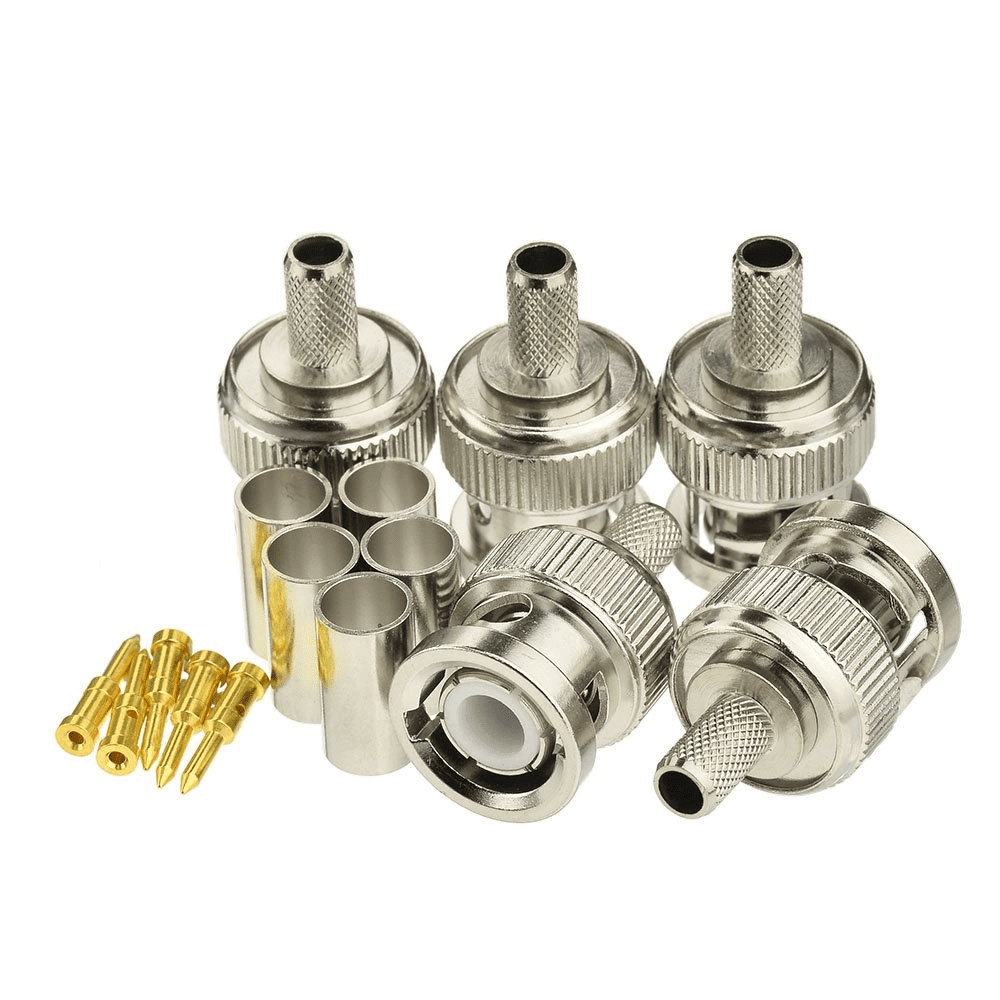
The characteristic impedance of the RF coaxial connector and the cable it connects must be consistent. There are two common characteristic impedances for coaxial cables: 50Ω and 75Ω. Each type of coaxial cable has a characteristic impedance tolerance range. Typically, the characteristic impedance tolerance for 50Ω flexible cable is ±2Ω, for 75Ω flexible cable is ±3Ω, and for 50Ω semi-rigid cable is within ±1.5Ω.
2) Dielectric Support Design
To support and stabilize the relative position of the center conductor and outer conductor, a dielectric support must be designed between the inner and outer conductors. Currently, dielectric support materials include polytetrafluoroethylene, polyethylene, and polystyrene. Because the weight of the dielectric support significantly affects electrical performance, the density consistency of the dielectric support material is required. Generally, dielectric supports machined from rod stock have better density consistency than those made by die-casting. Ensure that the characteristic impedance of the support section and the air section within the RF coaxial connector are consistent. That is, the characteristic impedance of each cross-section of the coaxial cable is consistent with the characteristic impedance of the connected cable.
 Dielectric Support Design and Coplanar Compensation
1) Structural Impact of Dielectric Support
In the first design phase, the calculation and impedance matching of the internal characteristic impedance of the RF coaxial connector were determined, which roughly determined the structural dimensions. However, due to the presence of the dielectric support and the difference between the dielectric constant (εr) of the support and the dielectric constant of air (ε0), the inner and outer conductors must be designed in a stepped pattern to ensure the same characteristic impedance across each cross-section.
2) Minimizing Discontinuity Capacitance
Discontinuity capacitance values vary depending on the specific processing scheme. Discontinuity capacitance can be minimized by properly combining the slot depths of the inner and outer conductors.
3) Coplanar Compensation
Although discontinuity capacitance can be minimized by adopting an appropriate slot depth combination at the inner and outer conductor supports during structural design, a small amount of discontinuity capacitance will still remain. To achieve minimal residual reflection over a wide frequency band, coplanar compensation is required. Coplanar compensation refers to the introduction of compensation at the discontinuity.
Transition from Large to Small Inner and Outer Conductor Sizes
1) Size Transition Issues
In connector design, transitions from large to small inner and outer conductor sizes are common. The sudden change in conductor cross-sectional area at the step causes significant reflections due to the step capacitance, necessitating compensation.
2) Examples and Compensation Methods
For example, this situation occurs in adapters such as 7/16-to-2.9-inch and 7/16-to-2.4-inch. Because the 7/16-inch type operates at relatively low frequencies (e.g., 1 GHz to 4 GHz), replacing the tapered transition with a right-angled step with an axial offset can achieve roughly the same electrical performance (standing wave ratio). There are two compensation methods: tapered overcompensation and an axially offset step transition.

